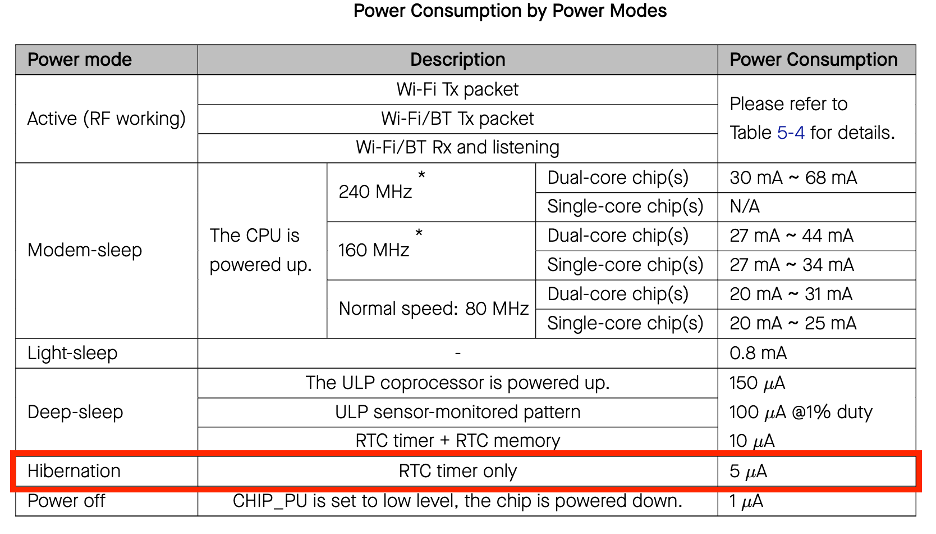
The term "Hibernate" for the ESP32 typically refers to the most aggressive deep sleep configuration aimed at minimizing power consumption to the lowest possible levels, often specified as approximately 5 µA. This state is achieved by powering down virtually all non-essential components.
Hibernate Mode
Although "Hibernate" is not always explicitly documented as a separate mode at the API level in Espressif’s official documentation, the term is widely used in community discussions and sometimes in technical descriptions to refer to the most aggressively optimized deep sleep configuration. This state aims to achieve the absolute minimum possible current consumption, which is usually around 5 µA. Achieving this level implies shutting down even the RTC memory and peripherals unless strictly necessary for the chosen wake-up source (e.g., only using the RTC timer).
What Happens in This Mode
In this ultra-low-power state, the ESP32 undergoes a radical power shutdown sequence. The main CPU cores (Xtensa LX6), the vast majority of RAM, and all APB_CLK-driven digital peripherals are completely powered down. This aggressive shutdown differentiates it from the light sleep mode, where the CPU state and RAM contents are preserved.

According to the datasheet, in Hibernate mode, only the RTC module remains powered, but even in that, some subsystems must be disabled to reach the 5 µA consumption target. Specifically, the SLOW and FAST memory subsystems, as well as peripherals and the external clock generator, are powered down.
Due to the nature of this mode (maximum shutdown of all peripherals), some important functional differences arise:
- Loss of Context: The CPU’s working context is lost upon wake-up. The chip performs a full reboot instead of resuming from where it was suspended.
- Power Consumption: Typically 4.9-5 µA with no extra components, ideal for timer-based data collection.
- Wake-up Sources: Only the timer based on the internal clock source is available.
- Wake-up Reason: Use
esp_sleep_get_wakeup_cause()to read the wake-up reason from the RTC controller.
Hardware Aspects
Achieving the ultra-low 5 µA power consumption in Hibernate mode is a complex task that depends on a combination of hardware design and careful software tuning. The specified 5 µA is the theoretical minimum for the chip itself, but practical implementations often struggle to achieve this.
Analyzing power consumption reveals a critical difference between the theoretical values from technical descriptions and practical measurements on standard development boards. While Espressif’s technical documentation cites deep sleep currents as low as 5 µA, actual measurements on typical ESP32 boards often show significantly higher consumption. For example, an ESP32-DevKitC may show 0.011 mA (110 µA) in deep sleep, while other boards, like the SparkFun ESP32 Thing or Ai-Thinker NodeMCU-32S, may consume 4–6 mA even in their lowest claimed Hibernate states.
This discrepancy is mainly explained by the auxiliary components present on development boards, including USB-UART converters, power LEDs, inefficient linear voltage regulators (LDOs), and external pull-up/pull-down resistors. Each of these components draws its own quiescent current, increasing the total power budget even when the ESP32 chip itself is in its lowest power state.
All examples and measurements in this article are based on two boards specially designed for deep sleep modes: the Micropowercore and the DeepSleep dev board.
- Micropowercore: This board is designed for battery-powered autonomous devices. It integrates a charging controller and an efficient boot/buck regulator. It has a stable Iq (quiescent current) of 17 µA.
- DeepSleep dev board: This board has the minimum necessary peripherals for stable and reliable operation of the ESP-WROOM-32 SoC. This enables efficient low-power operation without unnecessary LDOs, LEDs, and other peripherals.
Using these two modules together enables efficient and convenient operation of the controller in various low-power modes. Offloading the regulated power supply and charging subsystem to a separate board allows for effective measurement of the SoC’s own current consumption.
Software Aspects
The methods described in the article were tested in the PlatformIO (VSCode) development environment and are available in the GitHub repository linked at the end of the article. The Arduino framework was used for the sketch.
To configure deep sleep and Hibernate modes, we will use both standard Arduino Core ESP32 API methods and low-level power management functions from the ESP-IDF framework for more precise and careful shutdown of unused controller subsystems to reduce power consumption.
Arduino API
The classic pinMode(GPIO_NUM_XX, INPUT) method sets the input mode for the controller’s pins.
ESP-IDF Sleep API
esp_sleep_enable_timer_wakeup(): Enables the timer to wake up the controller from deep sleep mode.- Parameter: microseconds (XX seconds * 1,000,000).
esp_sleep_pd_config(): Manages power domains during deep sleep.- Parameters:
ESP_PD_DOMAIN_RTC_PERIPH- RTC peripherals (e.g., touchpad, some timers).ESP_PD_DOMAIN_RTC_FAST_MEM- RTC fast memory (ULP programs).ESP_PD_DOMAIN_RTC_SLOW_MEM- RTC slow memory (ULP data).ESP_PD_DOMAIN_XTAL- crystal oscillator (works in PlatformIO, often fails in Arduino Core).
- Options:
ESP_PD_OPTION_OFF- disable power.ESP_PD_OPTION_ON- enable power.
- Parameters:
esp_deep_sleep_start(): Transitions the ESP32 into deep sleep mode. Wake-up occurs from preconfigured wake-up sources (e.g., timer).esp_sleep_get_wakeup_cause(): Returns the reason for wake-up (e.g., timer, button, touchpad).
What is the ESP-IDF API?
ESP-IDF (Espressif IoT Development Framework) is the official framework for programming Espressif microcontrollers (ESP32, ESP32-S3, etc.). It’s a low-level SDK upon which Arduino Core and other wrappers are built.
ESP-IDF provides a powerful C API (and some C++) to control all hardware aspects of the ESP32:
- power management
- Wi-Fi and Bluetooth management
- file system
- OTA updates
- FreeRTOS
- GPIO, SPI, I2C, and other peripherals
In Arduino Core, these ESP-IDF API calls can be used directly, but they must be used carefully to avoid disrupting the Power Domain (refs) and prevent asserts.
In summary, the sketch configuration can be broken down into the following tasks:
- Disabling all unused devices on the microcontroller.
- Configuring the microcontroller’s pins.
- Setting wake-up parameters and entering hibernate mode.
Disabling All Unused Devices
// disable WiFi and Bluetooth
esp_wifi_stop();
esp_bt_controller_disable();
BluetoothSerial SerialBT;
SerialBT.end();
Additionally, disable serial output with:
Serial.flush(); // flush all serial data
delay(200);
Configuring the Microcontroller’s Pins
All unused microcontroller pins are set to INPUT mode and level LOW:
pinMode(GPIO_NUM_15, INPUT);
pinMode(GPIO_NUM_12, INPUT);
pinMode(GPIO_NUM_14, INPUT);
When configuring the low-power mode, we also use a set of low-level calls from the ESP-IDF framework. In hibernate mode, all peripherals are effectively powered down, but a subset of pins known as RTC_GPIO remains. These pins are used for the RTC subsystem, wake-up functionality, and other features. Below is the list of RTC_GPIO pins for the ESP32:
- SENSOR_VP - RTC_GPIO0
- SENSOR_VN - RTC_GPIO3
- IO34 - RTC_GPIO4
- IO35 - RTC_GPIO5
- IO32 - RTC_GPIO9
- IO33 - RTC_GPIO8
- IO25 - RTC_GPIO6
- IO26 - RTC_GPIO7
- IO27 - RTC_GPIO17
- IO14 - RTC_GPIO16
- IO12 - RTC_GPIO15
- IO13 - RTC_GPIO14
- IO2 - RTC_GPIO12
- IO0 - RTC_GPIO11
- IO4 - RTC_GPIO10
For configuring these pins, in addition to standard methods, a set of low-level calls from the ESP-IDF SDK is used:
rtc_gpio_isolate()- isolates the pin from digital logic to reduce leakage.rtc_gpio_hold_en/dis()- holds the pin level during deep sleep.rtc_gpio_pullup_en/pulldown_en()- enables pull-ups/pull-downs.rtc_gpio_init/deinit()- switches the pin to RTC mode and back.rtc_gpio_set_level/get_level()- controls the pin level.
These methods are used to fine-tune RTC subsystem behavior in hibernate mode and do not affect the Power Domain (refs) or cause asserts.
They only configure:
- digital GPIO logic
- pull-ups
- isolation from the Digital GPIO block
- They do NOT affect the PD reference count.
You can safely call these functions as often as needed without risking asserts (refs >= 0). If RTC_PERIPH is already powered off via esp_sleep_pd_config(), RTC GPIO configurations may stop working (wake-up, touchpad, etc.). This is because the RTC peripheral is physically powered down. However, it’s important to know it exists and can influence PD in other modes.
Setting Wake-up Parameters and Entering Hibernate Mode
In this final stage, we configure the RTC module itself to operate in hibernate mode. This includes setting the timer wake-up, disabling all unnecessary peripherals, and transitioning to sleep mode.
Setting the timer:
// enable timer to wake up the controller
esp_sleep_enable_timer_wakeup(wakeup_sec * 1000000ULL);
Disabling RTC peripherals:
// disable RTC peripherals, fast and slow memory, XTAL
esp_sleep_pd_config(ESP_PD_DOMAIN_RTC_PERIPH, ESP_PD_OPTION_OFF);
esp_sleep_pd_config(ESP_PD_DOMAIN_RTC_FAST_MEM, ESP_PD_OPTION_OFF);
esp_sleep_pd_config(ESP_PD_DOMAIN_RTC_SLOW_MEM, ESP_PD_OPTION_OFF);
esp_sleep_pd_config(ESP_PD_DOMAIN_XTAL, ESP_PD_OPTION_OFF);
Entering sleep mode:
esp_deep_sleep_start(); // enter sleep at this point
Controller Wake-up
The controller wakes up with a cold start, as if you had powered it off and then on again, except for one detail: at the time of wake-up, the RTC system contains a register that holds a code indicating the wake-up reason. In Hibernate mode, only two reasons are actually available: power-on and timer wake-up.
The reason is analyzed in the void check_wake_up() function and written to the WakeupStatus structure, which can be used on startup to determine the cause of the wake-up.
  enum WakeupStatus {
  WAKEUP_MODEM,
  WAKEUP_POWER,
  WAKEUP_TOUCHPAD,
  WAKEUP_ULP,
  WAKEUP_TIMER,
  WAKEUP_BUTTON1,
  WAKEUP_BUTTON2
};
  void check_wake_up() {
  esp_sleep_wakeup_cause_t wakeup_reason;
  wakeup_reason = esp_sleep_get_wakeup_cause();

  if (ESP_SLEEP_WAKEUP_EXT0 == wakeup_reason) {
    Serial.println("Waked up from ext0.");
    operation = WakeupStatus::WAKEUP_MODEM;
  }

  if (ESP_SLEEP_WAKEUP_TOUCHPAD == wakeup_reason) {
    Serial.println("Waked up from touchpad.");
    operation = WakeupStatus::WAKEUP_TOUCHPAD;
  }

  if (ESP_SLEEP_WAKEUP_TIMER == wakeup_reason) {
    Serial.println("Waked up from timer.");
    operation = WakeupStatus::WAKEUP_TIMER;
  }

  if (ESP_SLEEP_WAKEUP_ULP == wakeup_reason) {
    Serial.println("Waked up from ulp.");
    operation = WakeupStatus::WAKEUP_ULP;
  }

  if (ESP_SLEEP_WAKEUP_EXT1 == wakeup_reason) {
    uint64_t GPIO_reason = esp_sleep_get_ext1_wakeup_status();
    unsigned int gpio_pin_waked_up = (log(GPIO_reason)) / log(2);
    if (gpio_pin_waked_up == BUTTON_PIN1) {
      Serial.print("Button 1 triggered ... ");
      operation = WakeupStatus::WAKEUP_BUTTON1;
    }
    if (gpio_pin_waked_up == BUTTON_PIN2) {
      Serial.println("Button 2 triggered ... ");
      operation = WakeupStatus::WAKEUP_BUTTON2;
    }
  }

  if (operation == WakeupStatus::WAKEUP_POWER) {
    Serial.println("Wake up on power on");
  }
}
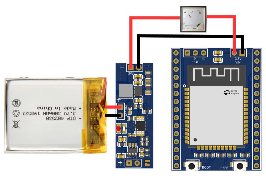
Test environment
To test the Hibernate modes, a dedicated test bench was assembled. The schematic of the setup is shown in the image.
Measurements were taken between the Micropowercore power board and the DeepSleep development board. Since the Micropowercore board itself consumes 17 µA, to eliminate its influence on the actual readings, the ammeter was connected between the power regulation/charging section and the DeepSleep board.
The DeepSleep board includes the minimal required circuitry to boot and run the ESP-WROOM-32 module reliably.
Conclusion
- RTC Controller: This is the main component that remains active, responsible for managing the internal timer and external wake-up events. It acts as the "brain" of the sleeping chip, waiting for a trigger.
- In Hibernate 5 µA mode, only timer wake-up is available. However, you can still determine the wake-up reason via the internal RTC register (
esp_sleep_get_wakeup_cause()). - In this mode, the controller will consume approximately 5 µA-this is the pure consumption of the ESP-WROOM-32 SoC itself. You must also add the consumption of your supporting circuitry, sensors, power board, etc.
Components and Sketches Used in This Article:
- Micropowercore: Charging controller and regulator board. https://micropowercore.com/
- DeepSleep dev board: Board with minimal components.
- Sketch: https://github.com/ deepsleepmicropowercore/ DeepSleep_v1_hibernate_5mkA