In the world of Internet of Things (IoT) and embedded systems, one of the most pressing challenges is achieving long battery life while using powerful microcontrollers. Many off-the-shelf development boards, while convenient for rapid prototyping, often include components such as USB-UART converters, indicator LEDs, or complex voltage regulators that consume significant quiescent current. This makes them unsuitable for truly low-power battery-powered applications.
Meet the DeepSleep dev.board — a board designed as a direct solution to this problem. The core idea was to create a development board with the minimal necessary set of components for normal and stable controller operation. This board is specifically designed for debugging ultra-low power consumption devices powered by batteries. Its specialized approach makes it an indispensable tool for developers where every microampere of consumed current directly affects device lifespan.
Where to buy?

Design philosophy: Why less is more
The foundation of the DeepSleep dev.board is a philosophy of minimalism aimed at achieving maximum energy efficiency. In the context of low-power applications, every additional component - even seemingly harmless ones like indicator LEDs or USB-UART chips — increases the overall quiescent current. This current becomes critically important when the main microcontroller is in deep sleep mode, as it can significantly reduce battery life.
The DeepSleep board intentionally omits these non-essential peripherals to achieve the lowest possible baseline power consumption. The direct benefits of this approach are clear: significantly increased battery life, reduced heat generation (especially important in compact enclosures), and smaller physical size. All these factors are key for portable and embedded IoT devices. The board is specifically designed for debugging ultra-low power consumption devices with battery power, which sets clear expectations about its optimal use cases.
Hardware overview: A detailed look at the DeepSleep dev. board
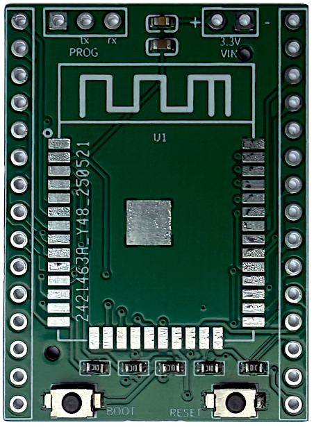
At the heart of the DeepSleep dev.board lies the ESP-WROOM-32 module. This module features a dual-core processor, integrated Wi-Fi and Bluetooth modules, and a rich set of peripherals (ADC, DAC, I2C, SPI, UART, etc.), making it a versatile and powerful platform for IoT projects, even with an emphasis on low power consumption.
The board features a compact form factor with dimensions of 29 mm x 39 mm.
The board operates at 3.3V, which is the native operating voltage for the ESP32. Two ceramic capacitors are provided at the input for power supply noise filtering. As seen in the schematic, these are C4 (22 µF) and C3 (0.1 µF). The larger capacitor (22 µF) provides bulk capacitance to smooth sudden current spikes (especially during Wi-Fi/Bluetooth transmission), while the smaller one (0.1 µF) acts as a decoupling capacitor, filtering high-frequency noise on the power bus and ensuring stable operation of sensitive digital circuitry.
The board also has several pull-up/pull-down resistors to prevent accidental entry into boot mode during operation. In the schematic, you can see:
- R7 (10 kΩ) on EN: Pulls the Enable pin high for normal operation
- R5 (10 kΩ) on GPIO12: Pulls GPIO12 low. This is a critical pin for boot mode selection; pulling it low ensures proper flash voltage during boot
- R6 (10 kΩ) on GPIO15: Pulls GPIO15 low. Another boot mode selection pin; pulling it low ensures proper boot mode selection
- R9 (10 kΩ) on GPIO2: Pulls GPIO2 high. This boot mode selection pin is often used for serial output during boot; pulling it high ensures normal operation
- R8 (10 kΩ) on GPIO0: Pulls GPIO0 high. This is the primary boot mode selection pin, which is pulled low by the BOOT button for flashing
All these decisions are aimed at ensuring reliability and stability in deployed, low-power contexts. Accidental entry into boot mode would render a deployed device useless and require physical intervention, which is impractical for remote or battery-powered applications. Similarly, noisy power can lead to intermittent failures, unstable wireless operation, or even data corruption — especially critical for battery-powered devices where power delivery may be less stable than from a wall adapter.
This is justified by the desire to create a reliable and predictable platform that can operate dependably for extended periods without supervision, which is paramount for true low-power IoT applications.
Getting started: Flashing the DeepSleep dev. board
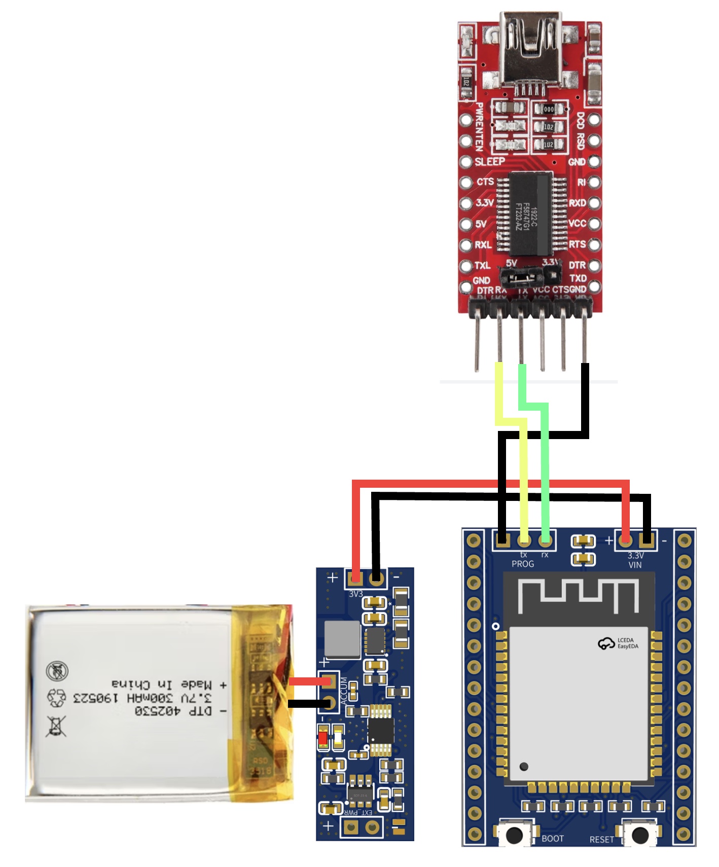
To upload firmware to the DeepSleep dev.board, an external FTDI232 module or similar USB-UART converter is required. This is necessary because the board's minimalist design intentionally excludes a built-in USB-UART chip to reduce quiescent current. It's crucial to ensure that the FTDI module is configured to operate at 3.3V. The jumper on the FTDI module should be set to the 3.3V position. Failure to do so (e.g., using 5V) can cause irreversible damage to the ESP32 module.
Since the board doesn't have automatic boot mode switching, this must be done manually. This is a direct consequence of the design philosophy aimed at minimizing components and power consumption. The procedure for entering bootloader mode and flashing is as follows:
- 1. Compile (build) the sketch in PlatformIO or Arduino IDE
- 2. Press the upload button in your IDE
- 3. Press and hold the BOOT button on the board
- 4. Press the RESET button once
It's crucial to complete the fourth step before your IDE attempts to upload the sketch to the board (usually "Connecting......" appears on screen). The board enters sketch upload mode immediately after hardware reset or power-on if the BOOT button is pressed and held at that moment.
The upload process isn't complicated, but it's important to understand how the bootloader works. This detailed explanation of the manual flashing process, including the reasons for manual execution (absence of auto-reset circuitry) and ESP32 bootloader operation principles (GPIO0 state during reset/power-on), provides better understanding of basic hardware mechanics and ESP32 boot sequences.
This will allow you to effectively troubleshoot when issues arise and appreciate the design decisions made to enhance energy efficiency. This board is primarily intended for developers who seek greater control and deeper understanding of their hardware, rather than a simple "plug and play" experience.
External programmer connection scheme
The programming connector (PROG) directly exposes the RX, TX, and GND pins from the ESP32 module to connector J3, confirming the need for an external FTDI module. The absence of a USB-UART chip directly contributes to minimal quiescent current.
Under the hood: Circuit explanation
The schematic is the ultimate blueprint of the DeepSleep dev.board design, revealing key components and their connections. The central component is the ESP32-WROOM-32 module (U1).
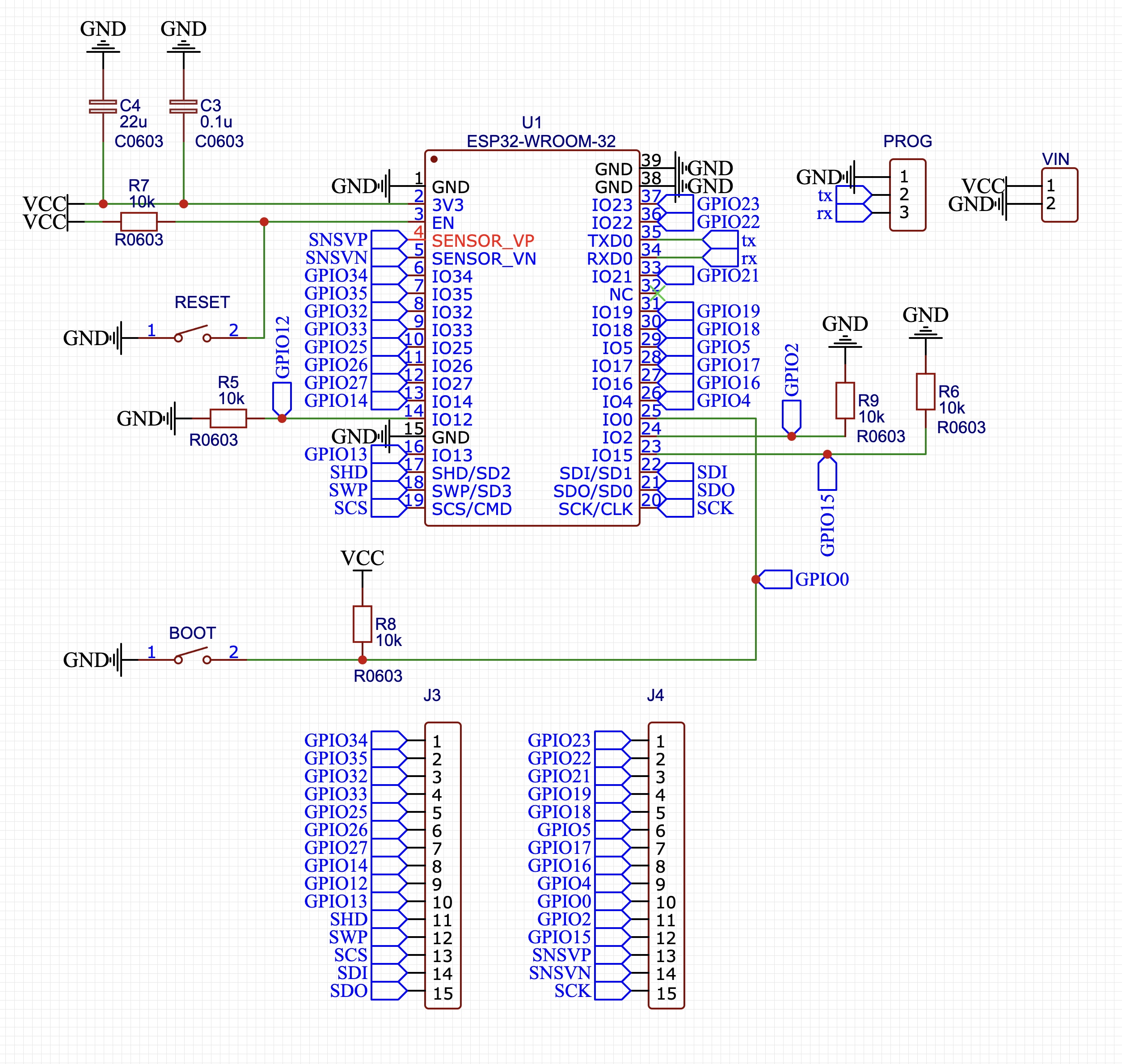
Power is supplied to the VCC bus, which is the 3.3V source for the ESP32. Capacitors C4 (22 µF) and C3 (0.1 µF) are connected to filter noise on the power line. These capacitors play a crucial role in ensuring stable voltage, which is critical for ESP32 operation, especially during peak currents consumed by Wi-Fi/Bluetooth modules. The VIN connector is directly connected to the VCC bus, confirming that the board expects a regulated 3.3V input voltage.
Reset and boot circuits are implemented using two buttons. The RESET button is connected to the ESP32's EN (Enable) pin through pull-up resistor R7 (10 kΩ to VCC). Pressing the RESET button pulls EN low, initiating a hardware reset. The BOOT button is connected to GPIO0 through pull-up resistor R8 (10 kΩ to VCC). Pressing the BOOT button pulls GPIO0 low, which combined with reset or power-on forces the ESP32 into bootloader mode.
Potential applications and use Cases
The DeepSleep dev.board, thanks to its unique characteristics, is ideally suited for a wide range of low-power and autonomous applications. Its strengths — ultra-low quiescent current, compact size, and reliable construction — make it the preferred choice for projects where energy efficiency and longevity are key factors.
Let's consider several scenarios where this board performs best:
- Remote Sensor Nodes: Deploying sensors (temperature, humidity, air quality, soil moisture) in remote or hard-to-reach locations where power sources are limited, requiring multi-year operation from small batteries
- Wearable Devices: Compact, low-power data loggers or simple communication modules for health monitoring, fitness trackers, or smart clothing, where minimal size and extended battery life are crucial
- Smart Agriculture Devices: Battery-powered soil moisture sensors, smart irrigation controllers, or animal tracking tags that transmit data infrequently
- Asset Tracking: GPS trackers or BLE beacons for valuable assets, vehicles, or equipment, where periodic location updates and very long battery life are essential
- Battery-Powered Home Automation: Wireless door/window sensors, motion detectors, or smart switches that must operate for years without battery replacement, easily integrating into existing smart home ecosystems
- Industrial IoT Monitoring: Devices for monitoring machinery, pipelines, or infrastructure in areas without easily accessible power, periodically transmitting critical data
In each of these applications, the specific advantages of the DeepSleep board - its ultra-low quiescent current, compact size, and reliable construction for stability — make it uniquely suitable compared to general-purpose development boards.
Conclusion
The DeepSleep dev.board represents a convenient board for developing low-power ESP32-based devices. Its main advantages are exceptional ultra-low power consumption, compact form factor, and enhanced stability achieved through thoughtful component selection, such as filtering capacitors and strategically placed pull-up/pull-down resistors.
This specialized approach makes it an invaluable tool for developers working on battery-powered IoT projects where every microampere counts. While it may require a slightly more hands-on approach compared to traditional development boards, the trade-offs in energy efficiency and deployment reliability make it an excellent choice for serious low-power applications.
Components used in this article:
- Micropowercore: Charging controller and regulator board.
- DeepSleep dev. board: Board with minimal components.